IPsec - Route based (VTI) PSK setup
This example utilises the new options available in OPNsense 23.1 to setup a site to site tunnel in routed mode between two OPNsense machines using a pre shared key.
Index
Network topology
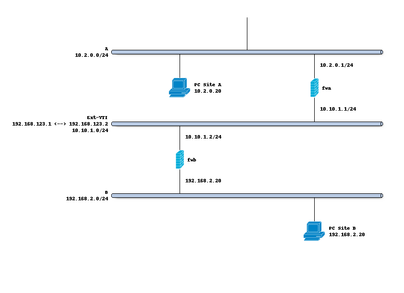
The schema below describes the situation we are implementing. Two networks (A,B) and a transit network (10.10.1.0/24)
to peer both firewalls. We will create a tunnel network using 192.168.123.1 [A] and 192.168.123.2 [B].
Preparations
Interface
In order to define our IPsec tunnel we do need to define a virtual tunnel interface () first.
The purpose of this device is to attach a tunnel to a security policy defined by its request id (reqid).
On both sites A and B we will add VTIs using the following parameters:
Property |
site A |
site B |
|---|---|---|
Reqid |
10 |
10 |
Local address |
10.10.1.1 |
10.10.1.2 |
Remote address |
10.10.1.2 |
10.10.1.1 |
Tunnel local address |
192.168.123.1 |
192.168.123.2 |
Tunnel remote address |
192.168.123.2 |
192.168.123.1 |
Note
Reqid should be a unique number within all configured if_ipsec(4) tunnels. The number 10 is arbitrary
Enable IPsec
Before configuring the connections, we enable the IPsec module. Just mark the “enable” checkbox on the connections tab.
Setting up the IPsec connection
In order to setup a simple (and common) IPsec connection, we go to and add a new entry.
General settings
Side by side the following general settings need to be set in this case, which configures the first part of the security association between both sites:
Property |
site A |
site B |
|---|---|---|
Local addresses |
10.10.1.1 |
10.10.1.2 |
Remote addresses |
10.10.1.2 |
10.10.1.1 |
Unique (advanced) |
Replace |
Replace |
Press <save> to go to the next step.
Authentication
Next we will need to add local authentication (add a new record in the local grid):
Property |
site A |
site B |
|---|---|---|
Authentication |
Pre-Shared Key |
Pre-Shared Key |
Id |
hostA |
hostB |
Then we need to set Pre-Shared Key for remote authentication as well:
Property |
site A |
site B |
|---|---|---|
Authentication |
Pre-Shared Key |
Pre-Shared Key |
Id |
hostB |
hostA |
Note
A pre-shared key needs to be added to “”. Set hostA for
local identifier and hostB for remote identifier.
While the remote identifier is optional, keep in mind that not specifying it will make this PSK elligible to be used for different connections using the same local ID as well. It is generally recommended to be as specific as possible.
Tip
If you have an ID specified in the Remote Authentication grid in a connection, then this connection now expects the other end to identifiy itself with this ID. Make sure this reflects reality, as some systems do not allow you to set a specific ID and can default to their local IP address instead.
Children
Finally we may add a child which will add security policies. Since our VTI tunnel matches on all traffic, both Site A and B use the same configuration which looks like this:
Mode |
Tunnel |
Reqid |
10 |
Policies |
[uncheck] |
Local |
0.0.0.0/0 |
Remote |
0.0.0.0/0 |
Start action |
Trap |
Warning
Make sure no policies are installed, when missing a passthrough and having policies installed one would not be able to access the firewall anymore as traffic will be trapped inside the tunnel.
Save and apply
Finally save the settings and hit apply on the connections page to establish the tunnel.
Gateways
Next step on both ends is to define a gateway () which reaches the other end of this channel, the
interface should be automatically created and is called ipsec10 in this example.
Both ends will need a gateway pointing at each other : Site A will need the following gateway:
Property |
site A |
site B |
|---|---|---|
Name |
IPSEC10_GW |
IPSEC10_GW |
Interface |
IPSEC10 |
IPSEC10 |
Address Family |
IPv4 |
IPv4 |
IP address |
192.168.123.2 |
192.168.123.1 |
Install firewall policies
With the tunnel active, all that remains is to accept traffic on this tunnel using the menu option.